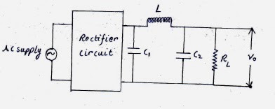
- LC FILTER
There is not much of an explanation left if you have understood how a inductor and capacitor filter works (working of both filters are given in my previous posts).Let's recapitulate,in an inductor filter the ripple factor is directly proportional to the load resistance but in capacitor filter it is inversely proportional to the load resistance.So the question is what happens if both are present in the same circuit.The answer is that in such a circuit ripple factor becomes almost independent of load resistance.The formula of ripple factor is given by the following expression...............................
From the formula it is clear that the ripple factor doesn't depends upon load resistance.
- Pi-Filter
There is one disadvantage in pi-filter which is that ripple factor depends upon load resistance whereas in LC filter it is independent.That's it!!!


No comments:
Post a Comment